Deepstomp’s User Manual
Table of Contents
- I. Device Overview
- I.1. Specification
- I.2. Standard Interface
- II. Running (Playing) Mode Operation
- II.1. Powering-On The Device
- II.2. ADC Calibration
- II.3. Adjusting The Input and Output Level
- II.4. Controlling The Effect’s Parameters
- II.4.1. Editing The Effect’s Parameters for Singe-Effect Application
- II.4.2. Editing The Effect’s Parameters for Multi-Effect Application
- II.4.3. Editing The Effect’s Parameters for Multi-Modal Application
- II.5. Preset Management
- II.5.1. Overview
- II.5.2. Loading Preset to The Active Setting
- II.5.3. Saving The Active Setting to The Preset Storage and Restoring The Customized Preset to The Default Value
- II.6. Guitar/Instrument Tuner Operation
- II.6.1. Overview
- II.6.2. Prerequisite
- II.6.3. Tuning Operation
- II.7. CPU Overload Indication
- III. Programming Mode Operation
- III.1. Flash Programming Tool
- III.2. Flash Programming Operation
I. Device’s Overview
Deepstomp is an open platform of programmable digital multi-effect stomp box/effect pedal. It employs ARM Cortex M3 for its core in the form of plug-able core module (blue-pill compatible), so you can upgrade the working effect by reprogramming the core or by plugging a new core board. It is specifically designed for electric guitar, but basically it can be used as general audio processor that accept wide range of input signal level, ranging from small signal from microphone (or any pickup) to standard line-out level signal from audio devices.
I.1. Specification
- Power supply: regulated 9-12V DC
- Plugable CPU board (Deepstomp core), which is “blue-pill” compatible (72 MHz STM32F1XX ARM Cortex M3, program flash memory: 64KB, RAM: 20 KB). There will be possible different specs from third party Deepstomp core vendor.
- Audio I/O conversion: 15/16 bit mono input/output
- Selectable input gain control range, low: 2-11x and high: 11-101x
I.2. Standard Interface
As an open platform, any vendors might implement their own design of device enclosure and its interface layout, but it should provide the following standard interface:
- 9-12V DC power supply plug port
- On/off power switch
- Hi/lo input gain range selector switch
- Program/run mode selector switch
- Rotary knob with push click
- Input level control knob
- Output level control knob
- Mono input plug port
- Mono output plug port
- Serial communication port (3.3V TTL level)
- True bypass stomp switch
- ADC calibration trimmer
- Power indicator LED
- Bypass (CHECK) indicator LED
- Control indicator LED bar (6 LEDs)
- Signal indicator LED bar (10 LEDs)
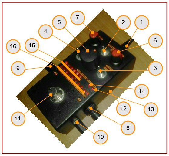
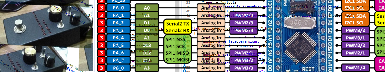
Since Deepstomp platform doesn’t specify any hardware interface layout standard, refer to the hardware interface layout documentation provided by the Deepstomp hardware vendor to identify each interface elements. For example, the hardware interface layout from Deeptronic’s Deepstomp kit is shown in the figure 1.
II. Running (Playing) Mode Operation
II.1. Powering-On The Device
- Set the power switch to “off” position, mode switch to “run”, and the gain range to “lo” position.
- Turn the input level and the output level knobs to their minimum (about 7 o’clock) position.
- Plug a 9-12V DC power source to the power supply plug port.
- Power-on the device by toggling the power switch to “on-position”.
- Make sure the power indicator LED (13) lights, if the power indicator LED doesn’t light then check the power supply voltage of your DC power plug and it’s polarity. After this power-on check up, now the device is ready to use.
II.2. ADC Calibration
When the device is used for the first time, it is necessary to calibrate the internal ADC circuitry to get the full resolution of the analog-to-digital conversion. This calibration method can also be repeated after long time usage or when the perceived digital noise are getting worse.
- Turn-off the device
- Set the mode switch to “run” position, the gain range switch at “lo” position, the output level knob at minimum (about 7 o’clock) position, and the input level knob at the center (12 o’clock) position.
- Connect the output of the device to the input of the device (loop back) using the standard male-to-male cable.
- Before turning-on the device, press and hold the rotary knob (without rotating it), then turn-on the device while holding the rotary knob press.
- Release the rotary know pressing about 1 second after the device get powered, now the device is running in ADC calibration mode, and 1 or 2 LEDs of both control indicator LEDs and signal indicator LEDs will be ON as an indication of this calibration mode. Make sure the effect is active (not bypassed, the CHECK indicator is ON), push the stomp switch if not.
- Turn the output level knob slowly to increase the output level until the control indicator LEDs (the 6 LEDs) show the centered indication (two center LEDs is ON). If the centered condition is hardly met then use the input level control to fine tune the level until get centered.
- Look at the signal indicator LEDs (the 10 LEDs), if the level is below the center then trim the calibration trimmer clockwise until get centered (two center LEDs is ON), do the opposite if the level shows above the center. If this step fails to center the indicator bar then it means the expansion circuit has too much imbalance, and you need to swap the operational amplifier chips (the two 741 op-amp chips) from their sockets.
- Turn-off the device, and now the device is ready to use.
- Note that the device is fully operable without this calibration procedure, but the resolution of the digital conversion might be worse than 15-bit, down-to 12-bit at worst. It might significantly affects the signal-to-noise performance of the device, and the noise could be badly perceptible when running a compression or expansion algorithm.
II.3. Adjusting The Input and Output Level
After power-on as described in the section II.1, the device will run in normal operation mode. This mode is indicated by no lights of control indicator LEDs (15), and the signal level indicator LEDs (16) shows the amplitude of the input signal in linear scale. Do the following steps to get the correct setting for the input and output level control:
- Bypass the effect by pressing the stomp switch to the CHECK indicator LED is OFF. Now the signal from the input is routed directly to the output.
- Play you guitar with the normal strumming power of your playing style, make sure the volume control of your guitar (pickup) is kept fixed at maximum for best signal-to-noise performance, and the guitar’s tone knob is fixed at your best preference. Adjust your amplifier volume for your convenience.
- With the output level control knob at minimum position (muted), activate the the effect by pressing the stomp switch (make sure the CHECK indicator LED is ON, the effect is not bypassed). Now the input signal is routed into the stompbox (but the output is muted), and the signal level indicator LEDs shows the input level.
- Strum you guitar at your realistic maximum power of your playing style, switch the gain range switch to low position, then adjust the input level control knob so the level indicator shows about level-8, and try not to get level-9 (overload). If your (realistic) maximum strumming power couldn’t get level-8 then switch the gain range to high position and readjust the input level knob. After this step, the input level control setting should be properly set.
- If the running application is a single-effect type then skip this step and go to step-6, but if it is a multi-effect or multi-modal type, then enter the tuner mode to bypass the signal in the software by pressing (without rotation) the rotary knob and hold (about one second) until the LED of the signal indicator at level-9 position blinks. If not the level-9 but the level-8 is blinking, then it indicates that the tuner works in silent mode because an accidental brief click is detected after releasing the rotary switch from hold, so you have to click the rotary knob briefly to toggle-back to software bypass mode for the tuner operation, and the level-9 indicator LED should blink.
- Play your guitar with normal strumming power, press the stomp switch to alternate between bypassed mode and not-bypassed mode, and adjust the output level knob until the perceived volume between the two modes are equal.
- If the running application is a multi-effect or multi-modal type then exit the tuning operation mode by pressing and holding (without rotating) the rotary knob until the blinking indicator is off, indicating that the device has been back to the normal operation mode.
After both input and output level of the stompbox is correctly set, now the volume of the guitar sound should be controlled only by the guitar amplifier or the processing equipment after the stompbox, so the level balance between the active effect and the bypassed will be preserved. The reason for getting a software-bypass mode( by entering the tuner mode) if the core is running a multi-effect or multi-modal type, is to get standard reference. Using a standardized reference, a custom output adjustment parameter can be designed for each presets or modes, and can be guaranteed that balancing the output level for all presets or modes will always be achievable by their designed adjustment range
II.4. Controlling The Effect’s Parameters
- II.4.1. Editing The Effect’s Parameters for Singe-Effect Application
- From normal operation mode, rotate the rotary knob one step to any direction, now one of the the control indicator LED (of the last accessed control) will light and the level indicator will show the last applied value of the controlled parameter.
- Rotate more in any direction and stop at the selected control of the associated parameter.
- Click (brief press) the rotary knob (without rotating) at the selected parameter, now the selected control indicator will blink to indicate that the associated parameter is in edit mode.
- Rotate the the knob to edit the parameter, and the effect operation will be applied in real time as you rotate the knob. Stop the rotation if the desired value is set.
- Click (brief press) the knob to exit the parameter edit mode and return to the normal operation. Please note that in every previous steps (1-4), if you do nothing for the next step within 4 seconds period then the edit mode will exit and back to the normal operation mode.
- II.4.2. Editing The Effect’s Parameters for Multi-Effect Application
- II.4.2.1 Controlling Method
- All the controlling method for editing the parameter, module, and preset described in the following sections (II.4.2.2, II.4.2.3, and II.4.2.4) are done in the same way as editing the single effect parameters described in the previous section (II.4.1).
- II.4.2.2. Assigned Parameters
- Control-1 to control-4 are assigned to the active effect module’s parameters.
- Control-5 is always assigned to the module selector.
- Control-6 is always assigned to the preset selector.
- II.4.2.3. Editing A Parameter of An Effect Module
- Activate the module you want to control by editing the control-5 value (the module selector)
- Edit the active module’s parameter editing using control-1 to control-4.
- II.4.2.4. Loading All Parameters for All Modules by Preset Selector
- Change the active preset value by editing the control-6 (the preset selector)
- II.4.2.1 Controlling Method
- II.4.3. Editing The Effect’s Parameters for Multi-Modal Application
- Multi-modal application is not implemented yet, this section is provided only for the future reference.
II.5. Preset Management
- II.5.1. Overview
- There are 19 presets that can be set by the application to provide default (factory settings), and each of them can be customized and restored back to the default setting. The preset location will be pointed by the level indicator from 0 to 9 in 19 steps (0, 0.5, 1, 1.5,…,9)
- II.5.2. Loading Preset to The Active Setting
- Loading preset to the active setting can be done in the same way as editing the effect parameter (refer to section II.4.1), just use the control-6 change the preset selector value. The active setting will be immediately loaded with the associated preset as you change/edit the preset value.
- II.5.3. Saving The Active Setting to The Preset Storage and Restoring The Customized Preset to The Default Value
- From the normal operation mode, rotate the rotary knob until the preset selector control is pointed, then press and hold it (about 1 second) until the the signal indicator blinks to show the last accessed preset.
- Release the hold, and then optionally rotate the knob if you wish to select the other preset location to store or to restore.
- Brief click the knob to store the active setting to the selected preset, or press and hold the knob until the blinking stops to restore the selected preset to the default setting.
- The operation now is back to the normal mode, and the signal indicator LED(s) should have stopped blinking as the indication of going back to the normal operation mode. If the signal indicator doesn’t stop blinking (usually after storing/brief click operation) then it means that the click is not detected, just repeat the brief click (with slightly longer period) until it done.
- If step-3 is not done until a period of 4 seconds expires then the operation will be reset back to normal operation mode without storing the active setting to- or restoring the preset.
II.6. Guitar/Instrument Tuner Operation
- II.6.1. Overview
- Guitar (or general musical instrument) tuner is capable of identifying standard western musical notes which consists of 12 semitones per octave, with deviation detection of 1/6 semitone accuracy. The first 7 (0-to-6) LEDs of signal level indicator will be used as notes indication. Single active LED would indicate C, D, E, F, G, A, or B notes, and 2 active LED would indicate semitones (C# = C+D for example). The note deviation of 1/6 semitone will be indicated by a single active LED of control indicator (LED1-to-LED6), and when the deviation is within (+-) 1/6 semitone from the center frequency then 2 LEDs will be activated (LED3+LED4) as the in-tune indication.
- II.6.2. Prerequisite
- Make sure the proper input level has been set before running the tuner mode operation (refer to section II.3)
- II.6.3. Tuning Operation
- From normal operation mode, press the rotary knob and hold (about one second) until the LED of the signal indicator at level-9 position blinks. Now the tuner mode operation is entered in software bypass mode (you can hear the musical instrument’s output as the tuning process is in progress).
- Optionally, you can click the knob (brief press) repeatedly to alternate the tuning mode between bypass mode and silent mode (the output will be muted during tuning process). When switched to the silent mode then the level-9 blinking indicator will be switched to level-8 blinking to indicate the silent tuning mode.
- Play a single note of your guitar (or instrument), and read the detected note in the signal indicator LEDs bar, and the pitch deviation in the control indicator LEDs bar. When the signal from your guitar or instrument is not detected within the last 1 second then the pitch deviation indicator will be OFF, and the detected note should be neglected, just play the note again to detect the note and the deviation again.
- After the tuning is done then press the rotary knob and hold (about 1 second) until the blinking indicator (level-8 or level-9 LED) is turned-off, as an indication that the tuner operation mode has exited back to normal operation mode.
II.7. CPU Overload Indication
When running a multi-effect application, activating several module combination at the same time might cause an overload on the CPU. This condition is indicated by the blinks of the last LED (of the 10 LED signal indicator bar) in the normal operation state (when it should be displaying the input signal level). The output might produce unpredictable sound characteristic but the operational menu would be fully operable, so just go to the parameter’s edit mode to deactivate some effect modules. Refer to the effect application’s documentation to find which parameter to be set (and at what value) to deactivate the module.
III. Programming Mode Operation
Programming the Deepstomp device with an effect application can be easily done through the serial communication port. A standard Deepstomp core board (blue-pill or compatibles) should be enabled for programming mode, but please note that some Deepstomp core boards might be disabled for programming mode for software protection, so please refer to the documentation of the core board from its vendor about its programmability.
III.1. Flash Programming Tool
- A Personal Computer (PC) with Windows OS.
- This manual only cover the flash programming using the flash loader program from STMicroelectronics that runs on a PC with Windows operating system. Other operating system such as Linux or others might be supported by other flash loader application from other vendor but is not covered in this manual.
- Flash Loader Demonstrator Software
- Download the software at https://www.st.com/en/development-tools/flasher-stm32.html, it is a free software (by email registration) from by STMicroelectronics. Follow their installation guide to install on your PC. Please contact us at hamuro at vidisonic dot com if the link doesn’t work.
- Serial (USB-to-TTL) Converter and Deepstomp Serial Connector Cable
- A serial (USB-to-TTL) converter is needed to convert the USB port into a serial TTL port, make sure the voltage level is set to 3.3V (usually by setting a correct jumper).
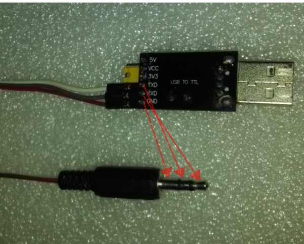
- Deepstomp serial connector cable is built using a standard (3.5 mm) stereo headphone jack and 3 single female header jumper cables. Wire each ground, L, and R terminals of the jack to a female header cable. Connect the header of the connector jack to the converter so the ground of the converter is connected to the ground of the jack, the TX of the converter to the middle ring of the jack, and the RX to the top pin of the jack (see Figure 2).
III.2. Flash Programming Operation
- Prepare the binary file of the compiled Deepstomp application. For example, you can use the open source version from “https://github.com/hamuro80/deepstomp/tree/master/software/deepstomp/Release/deepstomp.bin” or from third party vendor of the Deepstomp core.
- Switch-off the stompbox, and set the mode switch to “PROG” position.
- Connect the serial port of the stompbox to USB port of the PC using the USB-to-TTL converter connector.
- Run the flash loader software on the PC (“STMFlashLoader Demo.exe”), it would look like shown in the Figure 3.
- Set the correct port name, if the drop-down list show nothing then the USB-to-TTL converter is not detected by the PC, exit the flash loader application, unplug n plug again the converter, then go back to step-4.
- Set the baud rate to 115200, Parity: Even, Echo: Disabled, Timeout(s): 1, and now the GUI should look like shown in the Figure 4 (the port name could be different depend on your used USB port).
- Switch-on the stompbox.
- Click “Next” in the flash loader software. Now the software GUI would look like shown in the Figure 5. If the software give no response like shown in the Figure 6 then click OK, switch-off the stompbox, check the serial connection, and go back to step-7.
- After successfully connected to the stompbox in step-8, then click “Next” again and the software would show the core’s status as shown in the Figure 7. The Target drop-down list can be selected to match the core’s specification that specify the flash memory size. Select the option with 64K size to comply with the standard blue-pill (or compatible) board (specified for 64K in the data sheet), but some report it actually has 128K memory size so you can try to explore whether it works or not later.
- Click “Next” to continue, and now the GUI would look like shown in the Figure 8.
- Tick the radio button of the “Download to device” section, and browse the binary file of the compiled Deepstomp application by clicking the browse button inside the “Download from file” box.
- Inside the “Download from file” section box, check the options “Erase necessary pages”, set the start address “@ (h)” : 8000000, check the “Jump to the user program” and “Verify after download”, so the GUI would look like shown in the Figure 9.
- Click “Next” to start programming the flash, the loading and the verification progress will be shown and a success status will be displayed after get finished as shown in the Figure 10.
- Now the stompbox will automatically run the Deepstomp application and you can exit the flash loader software. Please note that you have to switch back the mode switch to “RUN” position before the next power-on your stompbox to run in normal mode.
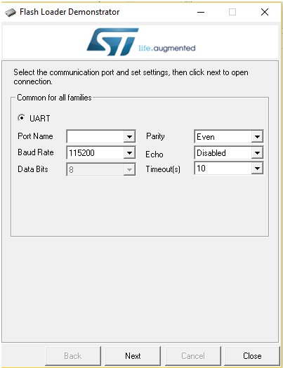
Figure 3. Flash Loader Demo Software 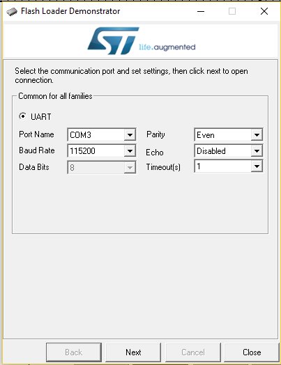
Figure 4. Serial Communication Setup 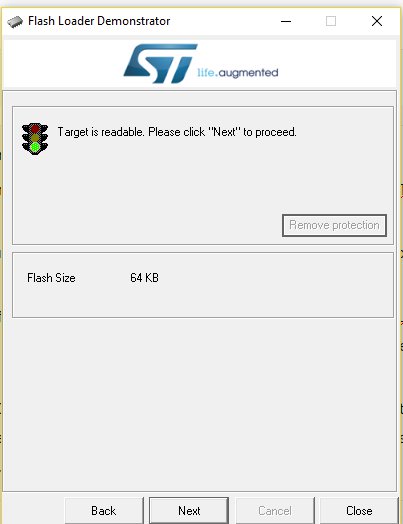
Figure 5. Stompbox Successful Connect 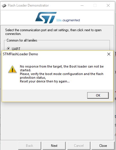
Figure 6. No Response Connection Status 
Figure 7. Device Status 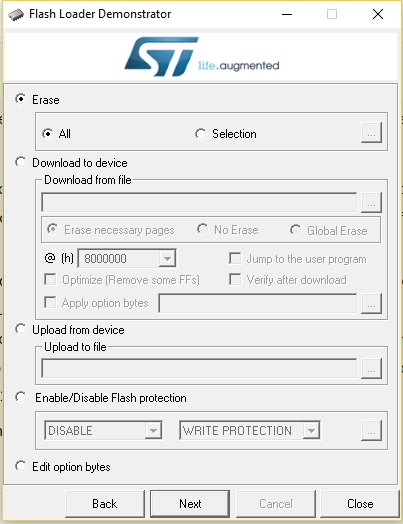
Figure 8. Programming GUIT 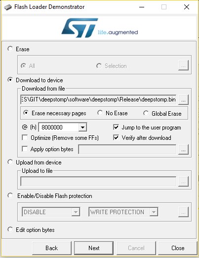
Figure 9. Programming Setup 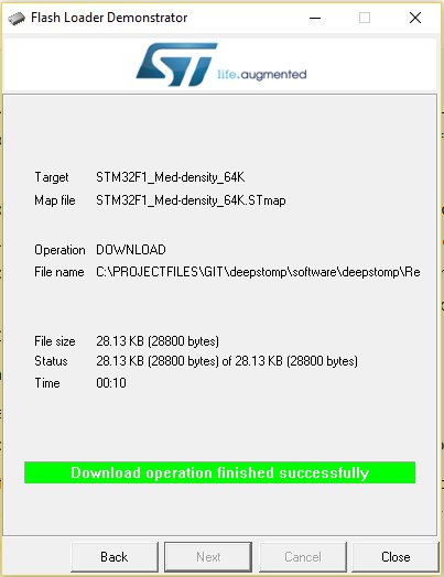
Figure 10. Programming Success
