Depstomp’s Hardware Manual
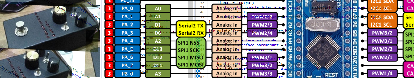
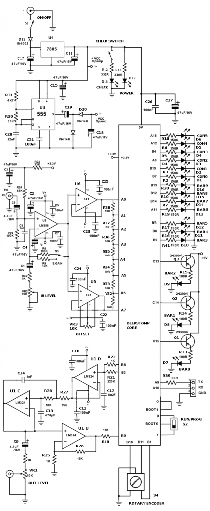
Deepstomp Main Board
Schematic Diagram (Version 1.2)
Standard Interface
As an open platform, any vendors might implement their own design of device enclosure and its interface layout, but it should provide the following standard interface:
- 9-12V DC power supply plug port
- On/off power switch
- Hi/lo input gain range selector switch
- Program/run mode selector switch
- Rotary knob with push click
- Input level control knob
- Output level control knob
- Mono input plug port
- Mono output plug port
- Serial communication port (3.3V TTL level)
- True bypass stomp switch
- ADC calibration trimmer
- Power indicator LED
- Bypass (CHECK) indicator LED
- Control indicator LED bar (6 LEDs)
- Signal indicator LED bar (10 LEDs)
Bill of Materials
- Resistors
- VR1,2 ……………………………………………………………. 2 x 10K Potentiometer
- VR3 ……………………………………………………………….. 1 x 10K Multi-turn trimmer potentiometer
- R1,22,25,42 ………………………………………………….. 4 x 1K
- R2,3,4,5,6,7,10,16,17,18,19,20,41 ……………. 13 x 150R
- R8,29 …………………………………………………………….. 2 x 100K
- R9,28,40………………………………………………………… 3 x 10K
- R11, R12 ………………………………………………………. 2 x 330R
- R13,14,15,39 ……………………………………………….. 4 x 100R
- R21 …………………………………………………………………1 x 220K
- R23, R30 ………………………………………………………. 2 x 33K
- R24 ………………………………………………………………… 1 x 68K
- R26,27 …………………………………………………………… 2 x 15K
- R31 ……………………………………………………………….. 1 x 4K7
- R32,33,34,35,36,37,38 ……………………………….. 7 x 10R
- Capacitors
- C1,2,3,4,15,16,17,18,19,27…………………………. 10 x 47uF/16V Electrolytic
- C5,7,10,11,21,22,23,24,25,26 ……………………. 10 x 100nF Mylar or 1uF Multilayer Ceramic
- C6,9 ……………………………………………………………….. 2 x 4u7/16V Electrolytic
- C20 …………………………………………………………………. 1 x 22nF Mylar
- C8,14 ……………………………………………………………… 2 x 1nF Mylar
- C12 …………………………………………………………………. 1 x 8n2 Mylar
- C13 …………………………………………………………………. 1 x 470pF Mylar
- Transistors
- Q1,2,3 ……………………………………………………………. 3 x 2N3904
- Diodes
- D19 ………………………………………………………………… 1 x 1N4002
- D20,21 …………………………………………………………… 2 x 1N4148
- D1,2,3,4,5,6,7,8,9,10,11,12,13,14,15,16,17,18 … 18 x LED (3 mm)
- Integrated Circuits (IC)
- U1 ………………………………………………………………….. 1 x LM324
- U2 ………………………………………………………………….. 1 x LM358
- U3 ………………………………………………………………….. 1 x 555
- U4 ………………………………………………………………….. 1 x 7805
- U5,6 ……………………………………………………………….. 2 x 741
- Switches
- S1,2,3 …………………………………………………………….. 3 x SPDT Toggle Switch
- S4 …………………………………………………………………… Rotary Encoder with Push Button
- CHECK ………………………………………………………….. 1 x 3PDT Stomp Switch
- Connectors
- IN …………………………………………………………………….. 1 x Mono audio plug port
- OUT ………………………………………………………………… 1 x Mono audio plug port
- Serial Communication …………………………………. 1 x stereo plug (3.5mm) port
- POWER ………………………………………………………….. 1 x DC power plug port
- CPU/Core board …………………………………………….. Blue-pill board compatible female header
Assembly Guideline
Please refer to the manual from the Deepstomp PCB/Kit’s documentation provided by the vendor.
